
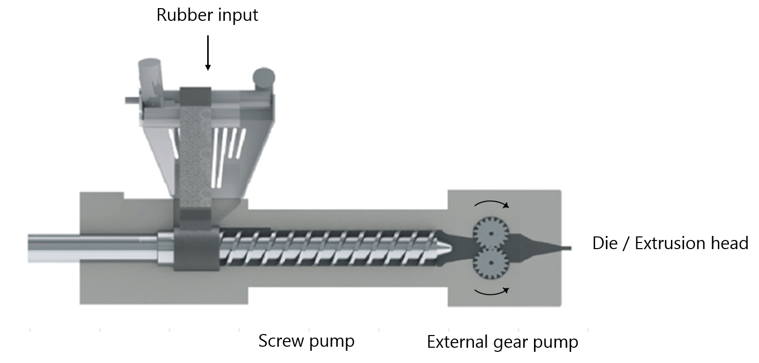
The rubber extrusion machine consists of a rubber input, a screw pump, the external gear pump and an extrusion head (Figure 1). The pulsation of the external gear pump is caused by its kinematics - i.e. the shape of the gears and its rotational velocity - and influenced by the fluid dynamics of the rubber, i.e. viscosity, compressibility etc. Since the preference of our client was to not change the shape of the gear, the rotational velocity of the gears is adapted using several periodic velocity curves as input. These input curves are tested using both CFD and experiments, afterwich the results were compared.
modelling the gear pump flow.
The CFD simulation is performed in 2D, to limit simulation times. The domain is shown in Figure 3 and is based on the geometry of the machine on wich the experiments are performed. A porous domain with a high resistance is added to the end of the domain to simulate the resistance caused by the extrusion head of the machine.
One of the main challenges of the CFD simulation was the mesh. Normally a stationary and rotating mesh combination is used for rotating geometries, but this approach is not possible as the two gears mesh together. Remeshing the geometry for each timestep proved to be very time consuming in both mesh time and simulation time. Additionally, the quality of the mesh was not good enough to resolve the high gradients of pressure and velocity between the teeth.
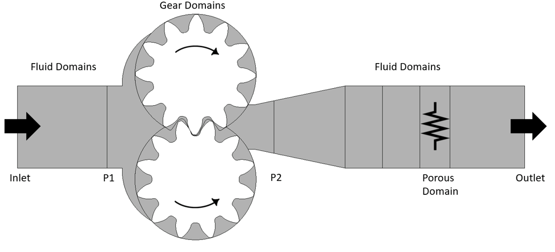
To solve this, the meshing software TwinMesh was used. Using TwinMesh we were able to create a structured mesh for each gear, that is ‘compressed’ between the teeth. The structure and element numbering is kept exactly the same between timesteps, only the rotation and compression is changed. This ensures that the simulation doesn’t need to interpolate the results of the previous timestep on a new grid, which greatly increases the accuracy and speed of the simulation.
Also the fluid behaviour of rubber needed some extra attention in this simulation. Rubber is non-Newtonian, which means that its viscosity changes with differing shear stress, pressure and temperature. This was all added to the material model, and special care was taken in velocity-pressure coupling in the solver to prevent instabilities due to the high gradients.
experimental analysis.
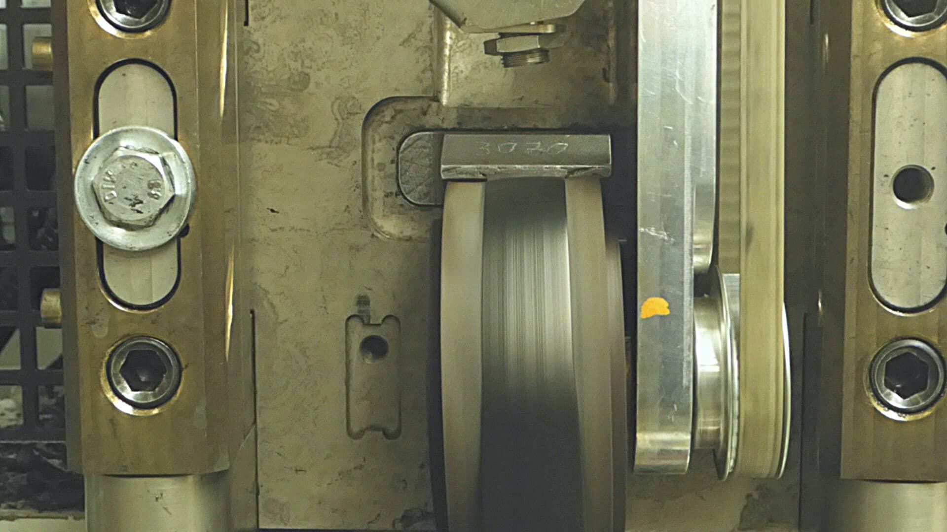
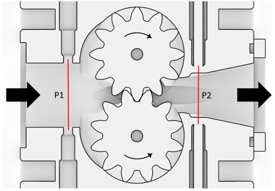
The set-up of the external gear pump is shown more detailed in Figure 4. The pressure sensors in the machine corresponds to the location where pressure is measured in the CFD simulation. The same velocity input curves are used in the experiments and the CFD simulations. Two different rubber compounds were used that have different non-Newtonian behaviours.
results.
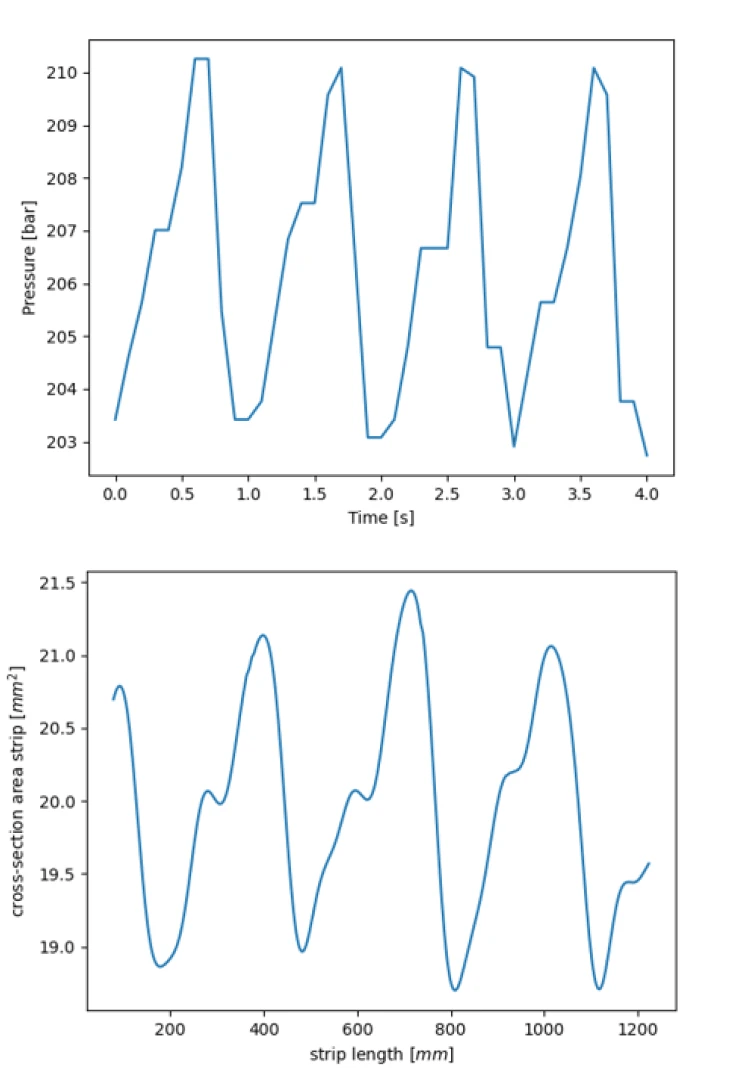
In the animation (Fig. 5) the working principle of the external gear pump is visible. A lower pressure rubber is fed into the pump (left). As the gears rotate, rubber flows along the outer walls to the higher pressure side of the pump (right). The interlocking teeth press the rubber towards the outlet. The periodicity of the interlocking teeth is clear from the graph in the animation. It shows the resulting pressure curve at the outlet, and looks very similar to the experimentally measured pressure and cross-sectional area curves that were shown in Figure 2.
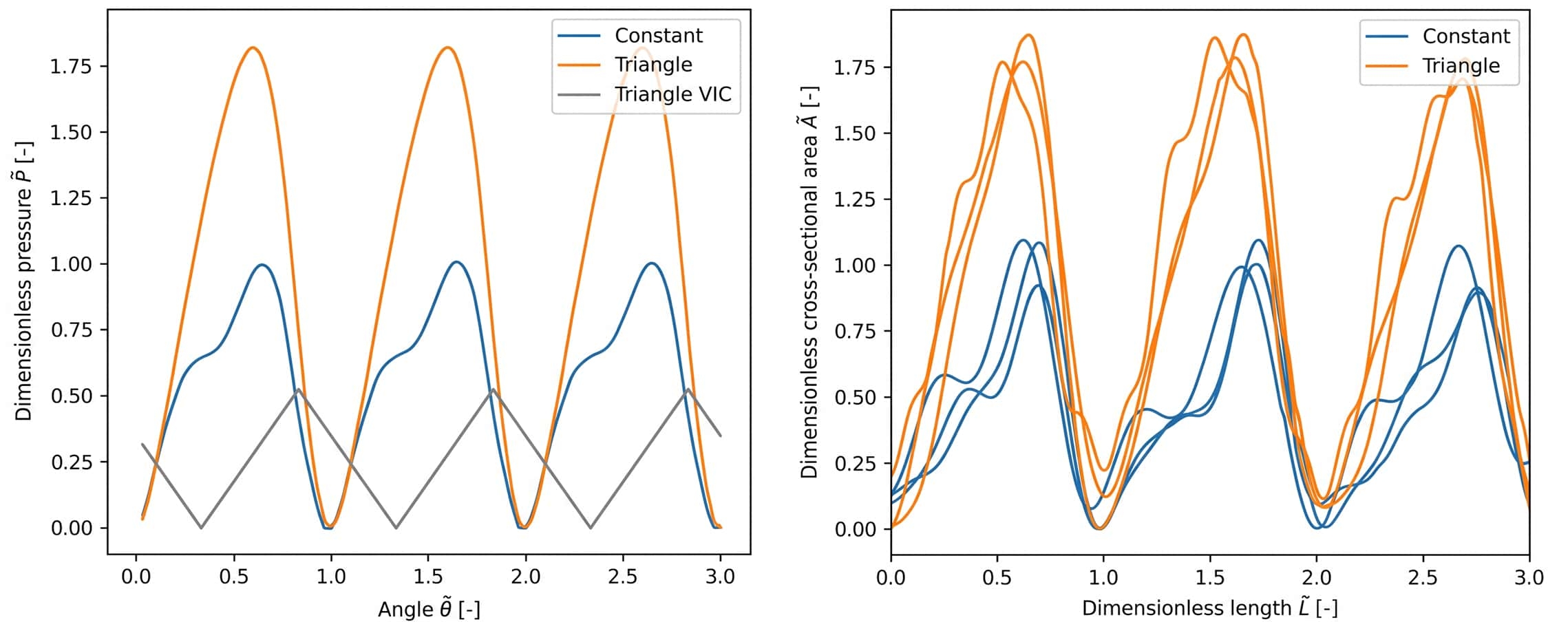
This simulation was performed using a constant rotational velocity for the gears. More interesting is what happens when the rotational velocity is changed periodically to change the resulting pulsation. Several input curves were tested, the triangle-shaped input curve is shown in Figure 6 as illustration. Figure 6 shows the pressure and cross section pulsation for constant rotational velocity in blue, with the simulation on the left and the experimental data of three separate runs on the right. Both plots are dimensionless and normalized, to enable comparison between the two data sets. In orange (right, Fig. 6) the varation in pressure and cross section as a result of the triangle velocity input curve (VIC) is plotted, which is plotted in grey in the left panel of Figure 6. The amplitude and shape of the pulsation change very similarly in both the experimental data and the simulation.
In conclusion, these simulations can be used to predict the behaviour of the pulsation, and can thus give an indication of the quality of the extruded rubber strip without any experiments. This simplifies the design process, and can save resources in both man and machine hours.
"visualizing flow"
Understanding the internal dynamics of a system can be a complex task, especially when only the output, such as the extruded rubber strip and a pressure sensor in this case, is available. However, the use of computational fluid dynamics (CFD) simulations proved to be invaluable in tackling this challenge. The CFD simulations of the pump provided a clear visualization of the internal fluid dynamics of the rubber, allowing for a deeper understanding of the pulsation behavior. Furthermore, the simulations facilitated the testing of a novel approach to modify the pulsation behavior, which would have been expensive to achieve through experimental testing alone. Remarkably, the simulation results were in excellent agreement with the experimental data obtained subsequently, underscoring the effectiveness of CFD simulations in addressing engineering challenges. This showcases the power of utilizing CFD simulations as a valuable tool in gaining insights and optimizing system performance in complex situations.