
simulation description.
The relevant physical quantities that were considered in the simulation are the local pressure and CO2 concentration, both in the module (pm and cm) and in the fibers (pf and cf). These four terms together determine the amount of CO2 captured by the fibers. Hence, the fiber domain and the module should both be included in the simulation (Figure 2). The sink term, which is the amount of CO2 that is entering the fibers per m³ of module can then be calculated locally. The sink term m (in kg/m³/s) into the membrane fibers is
m = αA' Δ(cp),
where α is the membrane permeance in kg/s/m²/Pa/mol, A' is the fiber area per volume of module, and Δ(cp) is the difference in partial pressure:
Δ(cp) = cm pm- cf pf.
Using these governing equations in the simulation, the flow within the module and the fiber was calculated.
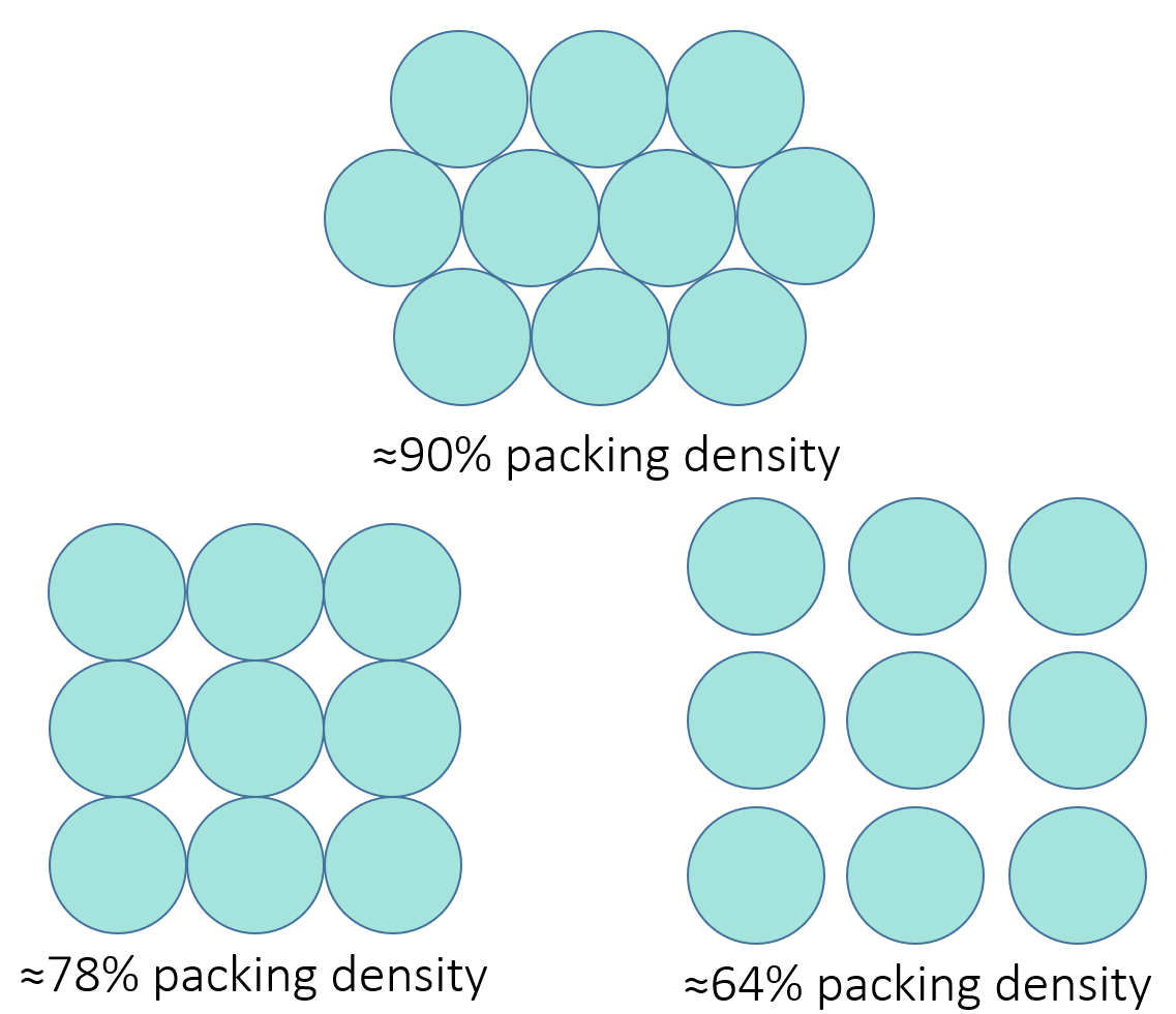
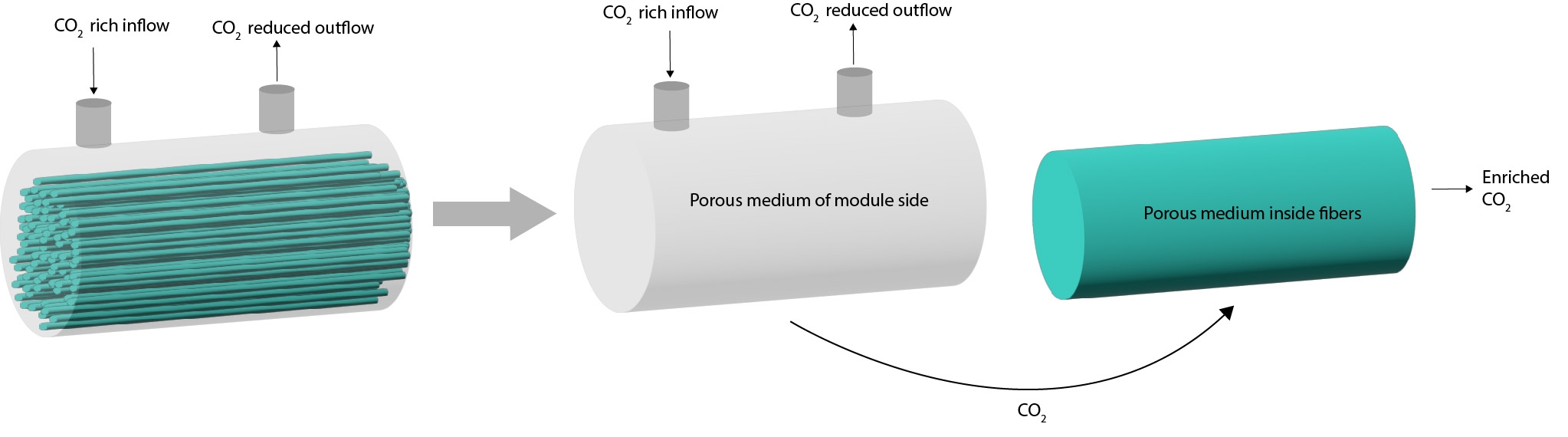
Simulating the pressure drop over 2000 fibers is computationally intensive, thus we simplified the simulation by modelling the fibers as a porous medium. Furthermore, only a small cell of the geometry was simulated in detail, to then use the calculated permeability in a macro model (micro/macro model approach). General information on micro/macro approaches can be found here. In the case of the fibers, the flow resistance is anisotropic. The flow along the fibers has a different resistance to flow compared to the flow perpendicular to the fibers. Both of these properties were calculated for different packing densities to determine the pressure drop over the module (Figure 1).
Hence, the packing density is an explicit choice in the module design, and depends on the amount of fibers and the space available inside the module. Combining the calculated permeability of the fibers with the larger geometry of the module results in a functioning macro model of the membrane. The inputs are the mass fraction and flow rate of CO2 at the inlet, the pressure at the outlet, and the pressure of suction at the end of the fibers. The outputs are the full flow field, pressure distribution, mass fraction distribution and the amount of CO2 that is captured within the fibers.
simulation result.
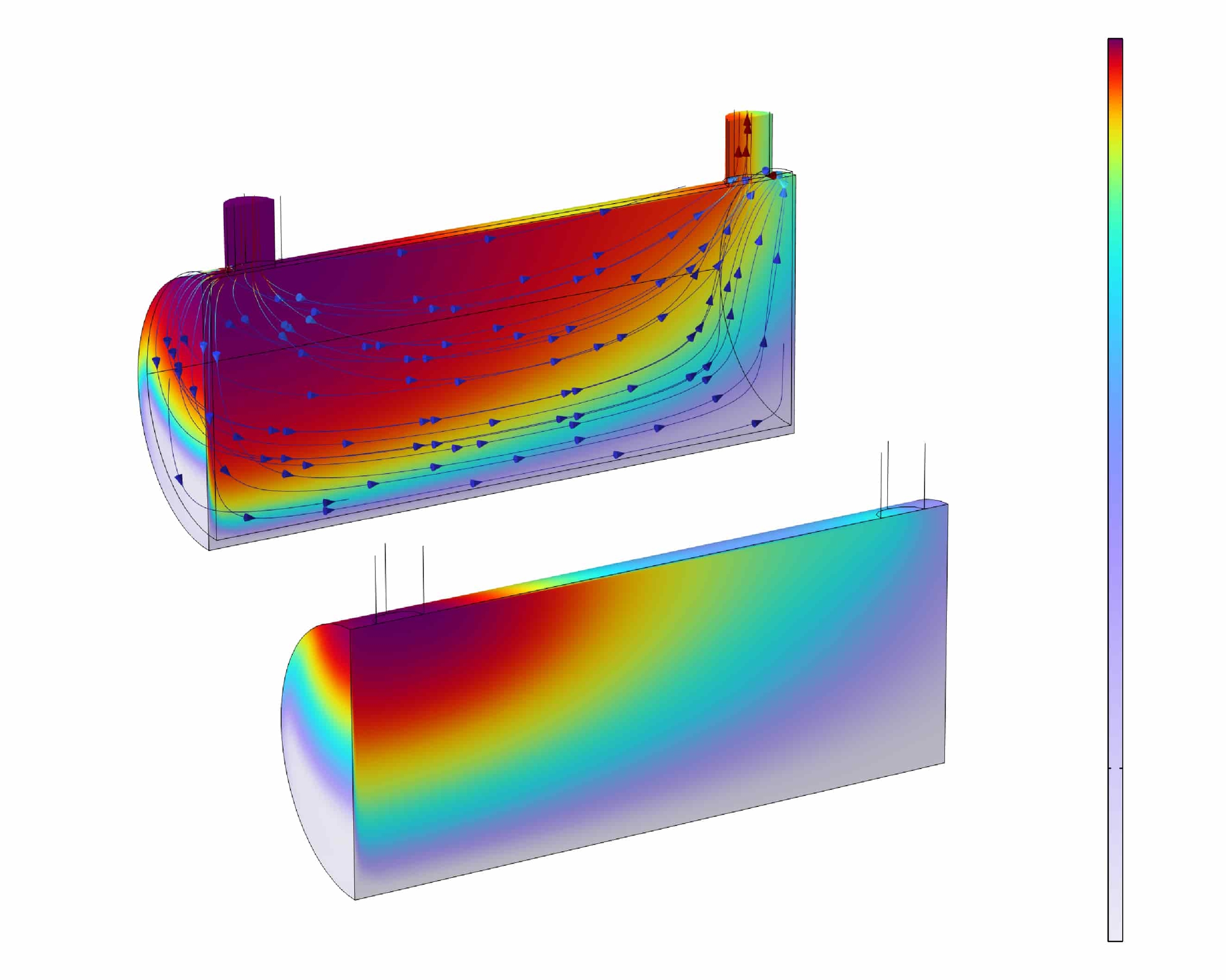
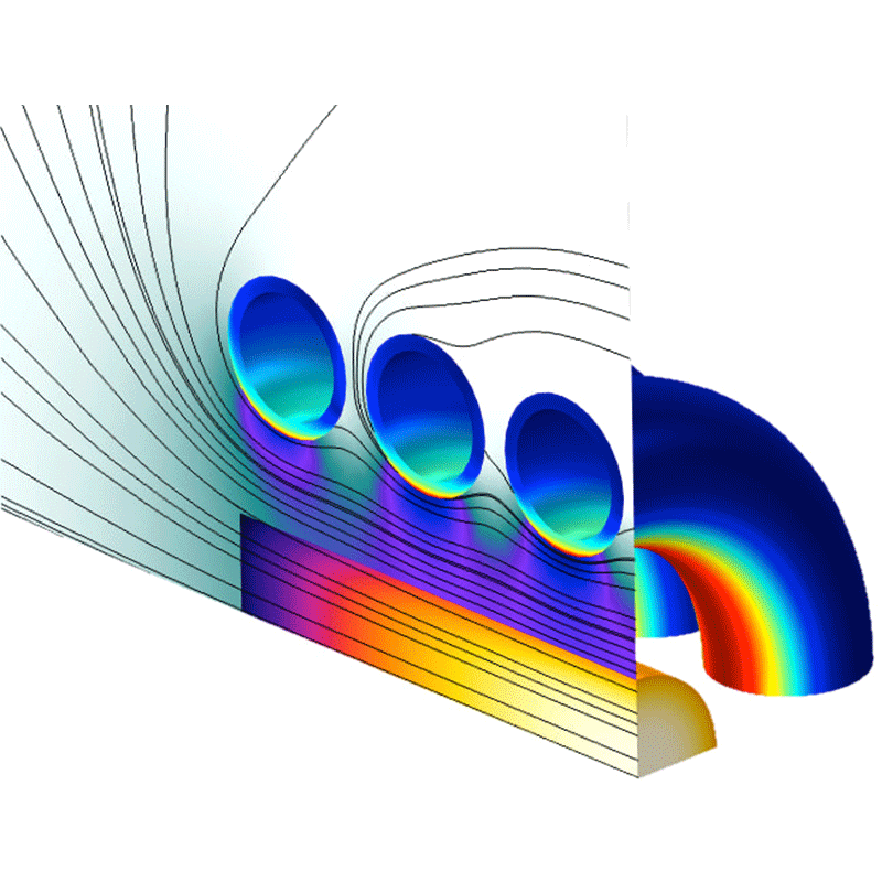
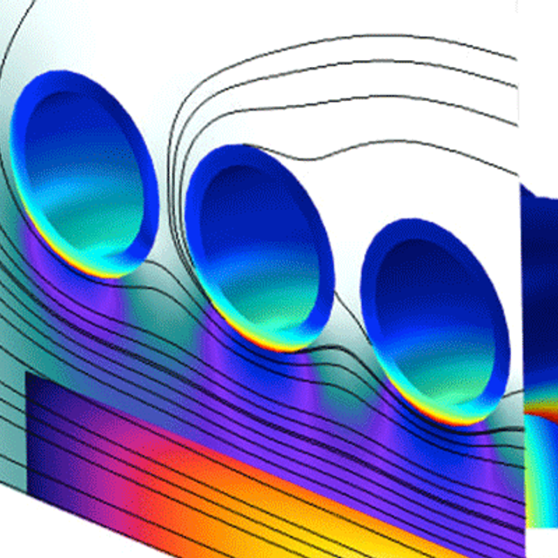
The result of the simulation, when applying all above mentioned boundary conditions, can be seen in Figure 3. The concentration of CO2 on the module side decreases across the module. At the same time, the CO2 emerges on the fiber side, locally increasing the concentration before flowing out of the module. This indicates that the module is working as intended and is extracting CO2 from the feed flow.
aqualung’s use of CFD to optimize module design.
Using CFD simulations, input parameters such as module geometry, fiber packing density, and process parameters can be quicky iterated to optimize the module. This means that the module can be tuned for specific industrial processes. In this way, a cost-benefit analysis can be performed, assessing CO2 capture purity and mass flow CO2 on the one hand, and the costs such as pumping power and size of the module on the other hand.
In simulations of filtering processes, it is very important to understand the relevant physics driving the membrane filtering. Different membrane processes could for example be driven by pressure, concentration of different species, temperature differences or velocities. We can incorporate this in our simulations. If you have a filtration or membrane technology problem, which you would like to optimize, you can contact us.
"physical problems with relevance for tomorrow"
Not only did this project contain interesting physics and computational challenges, but the resulting end product is relevant for today’s challenges. With our engineering skills we develop climate saving technologies, so that not only we, but also the next generation can enjoy the wonders of physics. What we call at Demcon ‘shared value’.
Herausforderungen, die wir meistern.
Demcon multiphysics.
Demcon multiphysics is an engineering agency with high-end expertise in the area of heat transfer, fluid dynamics, structural mechanics, acoustics, electromagnetism and nuclear physics. We support clients from a wide variety of market sectors and help them achieve their goals in research and development with deep physical insights.
We combine fundamental physical knowledge from an analytical approach with Computer Aided Engineering (CAE) simulations tools from ANSYS, MATHWORKS, COMSOL, STAR-CCM+ and FLUKA to setup, execute, analyze and evaluate numerical simulations. The use of Computational Fluid Dynamics (CFD), Finite Element Analysis (FEM / FEA), Lumped Element Modelling (LEM), Computational Electromagnetics (CEM) and Monte Carlo simulations enables us to make a virtual prototype of your design. With these techniques we can simulate the fluid and gas flows, energy exchange, heat and mass transfer, stresses, strains and vibrations in structures and the interaction of electromagnetic fields with other physical aspects like heat generation. Simulation-driven product development increases the development efficiency and reduces the product development time. Our services can therefore fully support you in the designing phase, from idea up to prototype, from prototype to final design.