

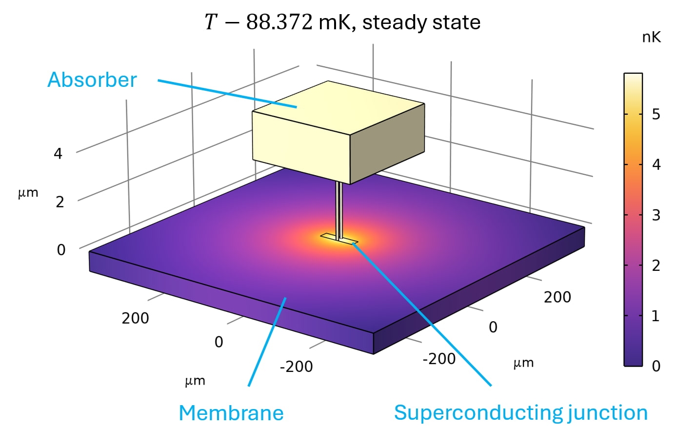
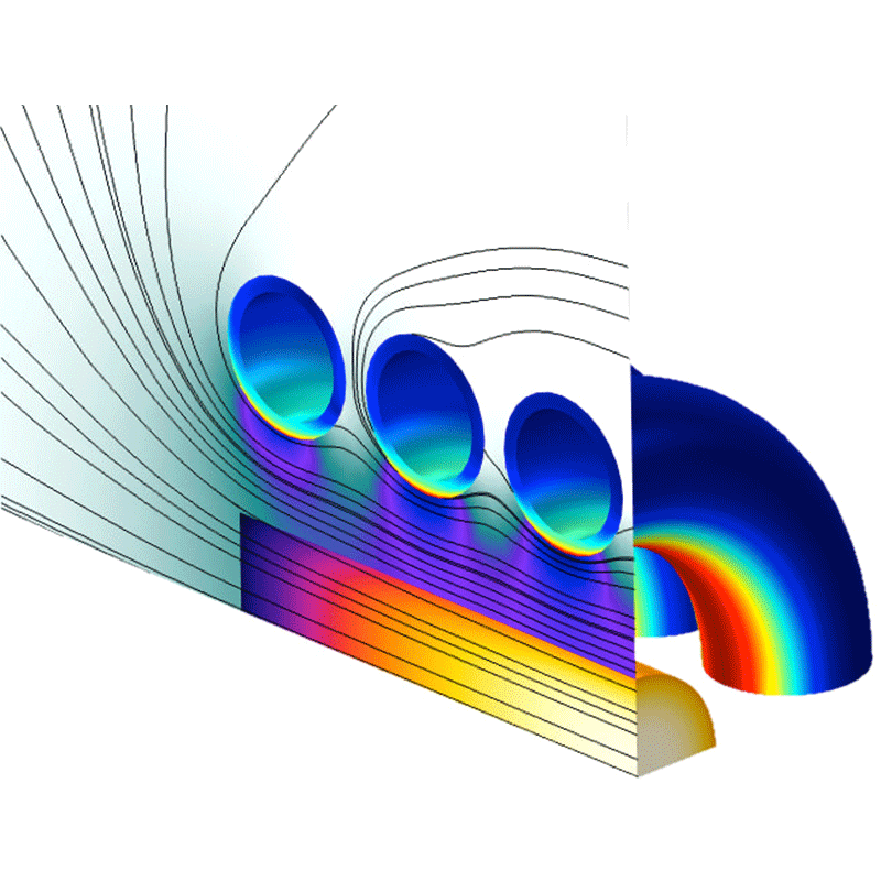
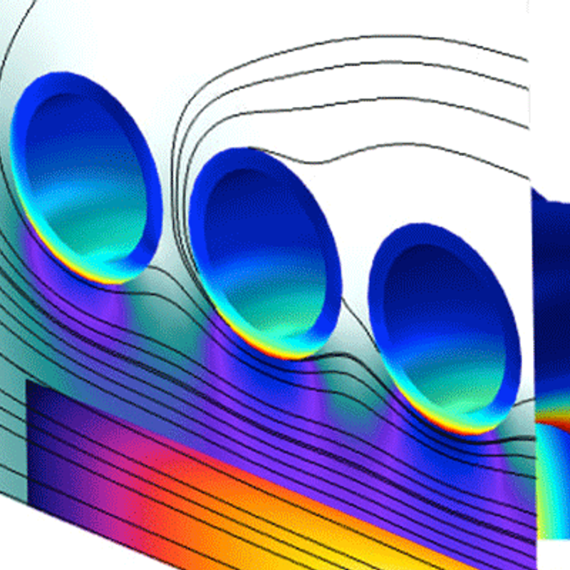
basic design of a TES microcalorimeter.
Figure 1 shows the temperature distribution in the heart of the device, for a very basic geometric design. The absorber can absorb incident photons and thereby heats up. It is thermally coupled to a thermometer: a superconducting ‘resistor’ RTES that is kept at its ‘transition edge’ between superconducting and normal state. When a photon hits, the resistance RTES (I,T) changes. The electrical circuit that is connected to the TES makes sure it keeps operating at the transition edge (explained further on). The device is situated on a membrane that provides a weak thermal coupling to a thermal bath (here 53 mK). This makes sure equilibrium is restored some time after a photon is absorbed, and the device is ready to absorb the next one. This coupling goes via ballistic phonon transport, so the heat rate scales with T 4 - Tbath4.
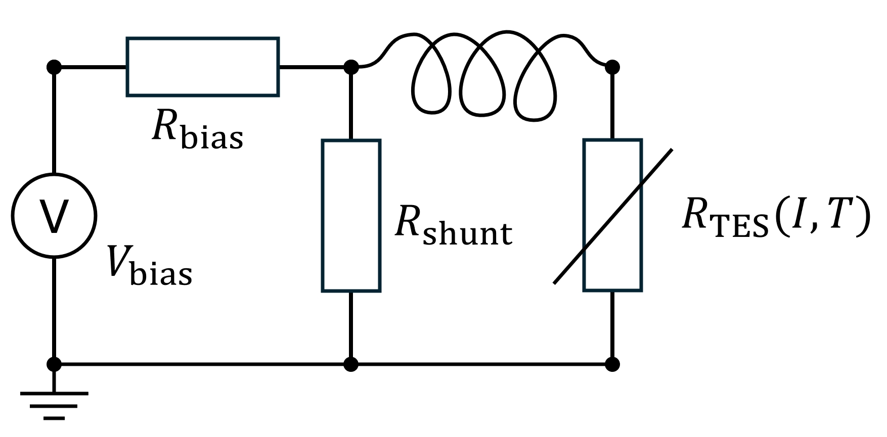
negative electrothermal feedback.
Figure 2 shows the circuit driving a TES microcalorimeter. The resistances are engineered such that Rbias >> RTES >> Rshunt so that in steady state the TES is basically voltage controlled with VTES ≈ Vbias Rshunt / Rbias. The dissipation in the TES is then:
PTES = (VTES2) / (RTES(I,T))
meaning: when T rises, the dissipation decreases and when T falls, the dissipation increases, i.e. negative electrothermal feedback. This keeps the TES at its transition edge.
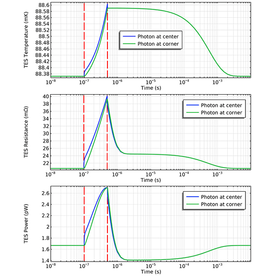
how the energy of a photon is measured.
When a photon hits, this adds energy in the form of heat to the system and causes a transient behaviour in the circuit that temporarily lowers the power fed in by the voltage source (after a very short pulse of higher power, see figure 3). This power PTES(t) is measured and the difference with the equilibrium value PTES,eq integrated over time:
Q = ∫ (PTES,eq - PTES(t)) dt
This energy can be related to the photon energy.
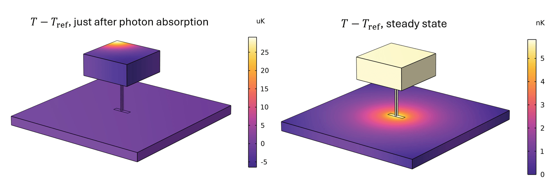
model purpose: very accurate energies.
The purpose of the model is to predict the dependence of the measured energy on the location where the photon hits the absorber. This is one of the factors that determines the energy resolution of a TES. As mentioned above, the desired energy resolution for 1 keV photons is typically around 1 eV. The model should be much more accurate than that, in this case the goal was 1 ppm accuracy in the measured energy Q. Note this is a time-dependent model that uses about 1000 timesteps from start to end. This means that the (additive part of) the error should be below 0.001 ppm. Besides, the temperature differences within the modelled geometry are of the order of nanokelvins, while the absolute temperature is ~ 0.1 K. One can imagine a naïve approach, solving for the absolute temperature, would thus give problems related to machine precision.
Modelling challenges.
The thermal FEM model is coupled to some ODE’s describing the electrical circuit. The key ingredient coupling the electrical and thermal behaviour is RTES (I,T), which is based on measurements. Interpolation noise cannot be tolerated in light of the requirements stated above. This is why first a suitable analytic fit function was determined to represent RTES (I,T).
The issue with the vast range of ∆T’s described above was solved by letting the model solve for a variable that represents T-Tref instead of absolute T. The reference temperature Tref is chosen to be the temperature at the corner of the part of the membrane in the model. This is not a fixed value, but added in the model as a degree of freedom which is thus also time-dependent and solved for.
The output of the model is not just simply PTES(t), because that would again cause too much interpolation noise when determining the energy in post-processing. Therefore, the system of equations is augmented with some equations for energies that are integrated while the model solves, and thus also subject to the same adaptive time stepping tolerances as other variables in the model.
These were the three main ingredients that enabled output energies with sub-ppm (numerical) accuracies.
Summarizing, we have successfully developed a high accuracy FEM model for transition edge sensors in COMSOL Multiphysics. The model is used by SRON to perform design iterations to optimize the energy resolution. This work has led to an (open access) publication in Journal of Applied Physics:
‘Modeling the effects of position dependence in large-absorber x-ray TES microcalorimeters’ (J. Appl. Phys. 138, 034504 (2025)).
"a niche application that required some creative tricks"
I found the physics of a TES quite interesting. It is a niche application that required some creative tricks to get the simulation to behave properly. Such a puzzle is in itself already satisfactory to complete successfully. Adding to that, SRON was very happy with the resulting model, being able to do the design iterations they intended to do with the model. And it led to a publication.
Herausforderungen, die wir meistern.
Demcon multiphysics.
Demcon multiphysics is an engineering agency with high-end expertise in the area of heat transfer, fluid dynamics, structural mechanics, acoustics, electromagnetism and nuclear physics. We support clients from a wide variety of market sectors and help them achieve their goals in research and development with deep physical insights.
We combine fundamental physical knowledge from an analytical approach with Computer Aided Engineering (CAE) simulations tools from ANSYS, MATHWORKS, COMSOL, STAR-CCM+ and FLUKA to setup, execute, analyze and evaluate numerical simulations. The use of Computational Fluid Dynamics (CFD), Finite Element Analysis (FEM / FEA), Lumped Element Modelling (LEM), Computational Electromagnetics (CEM) and Monte Carlo simulations enables us to make a virtual prototype of your design. With these techniques we can simulate the fluid and gas flows, energy exchange, heat and mass transfer, stresses, strains and vibrations in structures and the interaction of electromagnetic fields with other physical aspects like heat generation. Simulation-driven product development increases the development efficiency and reduces the product development time. Our services can therefore fully support you in the designing phase, from idea up to prototype, from prototype to final design.